|
|
|
|
Click on a category to view more information of trouble shooting tips and helpful information for fluid power systems. If you need further assistance, please contact us.
This is the most important consideration when installing the cylinder. When cylinders are shipped, the ports are usually securely plugged with plastic plugs which should not be removed until the piping is to be installed. All piping should be thoroughly clean, to include the removal of all threading and flaring burrs or chips, before making the connection to the cylinder ports. One chip can cause premature failure of the cylinder or other hydraulic system components.
Improper alignment will result in excessive cylinder wear. Check to assure rod alignment between the cylinder and its mating component on your machine in both the extended and retracted positions.
Cylinders operating in areas where there is weld splatter, fast drying chemicals, paint, excessive heat or other hazardous conditions, should have covers or shields to prevent damage to the rod and rod seals
Air with the cylinder or system will cause erratic operation of the cylinder. Most cylinders generally do not require bleed ports if the cylinder ports are mounted in an upright position. Several full strokes of the cylinder will purge air from the cylinder into the circuit piping, where it can be bled off. Bleeder ports are available for applications where the cylinder is the high point of the circuit or where the cylinder does not complete a full stroke during its normal cycle.
The use of high strength alloy steel mounting bolts 1/16” smaller than the hole size is recommended. After final alignment, foot mounted cylinders should de dowel pinned in place.
Lubricated pillow blocks designed for close tolerance applications should be used. It is important to rigidly mount and align the pillow blocks so that the trunnion pins will not be subjected to any extreme bending moments. The rod end should be pivoted with the pivot pin in line and parallel to the axis of the trunnion pins.
The use of high strength alloy steel mounting bolts is recommended. Shear keys should be used to reduce the stress on the mounting bolts created by the normal push and pull forces created by the cylinder cycle.
The controlled diameter rod busing extension can be used as a pilot to locate the flange mount. Dowel pins should be used after the cylinder is mounted and aligned to prevent shifting.
This type of cylinder must be pivoted at both ends and the pins must be in line and parallel to each other. After the cylinder is mounted, the customer should check to assure that the cylinder is free to swing through its working arc without interference from other machined parts.
When changing rod seals, extend the piston rod 3” or more if possible, being sure to support the rod at all times. Remove the retainer plate screws (if tie-rod nuts have to be removed, refer to the nut torque specification on this page when reassembling the cylinder), retainer plate and outer bushing. Using an eye hook or thin screwdriver, pry the vees from the end cap cavity (if low pressure air is applied to the rod end port, this will help to force the vees from the cavity). The new set of vees should be assembled into the cavity separately and lubed with soft vee in the center. Replace the rod wiper in the busing and reassemble the cylinder.
When changing piston seals, extend the piston rod 3” or more if possible, being sure to support the piston rod and the piston at all times. *Remove the tie-rod nuts, blind end cap, the barrel and the piston seals. A light grease, compatible with the system fluid, grease, compatible with the system fluid, should be used on the rings and block vee seals for smooth assembly. Install the block vee piston seals, scarf cutting on only the back-up washers. Then install the cast iron rings with the joints in opposite directions. To reassemble start the piston into the tube, compressing the cast iron rings using twine or a ring compressor. When the piston block vee seal is to the edge of the barrel, use a thing rounded blade to start the lip of the block vee, making sure the entire lip is started before moving the piston further into the tube.
When replacing barrel seals, use the same method of disassembling the cylinder as used when replacing piston seals. The barrel seal consists of a backup washer and O-Ring, which is assembled on the first step of both ends of the tube, with the backup washer going on first. The outer diameter of the tube groove on the end caps must be checked for nicks or burrs and then greased. Position the end caps squarely on the tube (check to make sure port location is correct) and firmly force or tap the end cap over the tube until it bottoms. Check to make sure the O-Ring did not shear and then finish assembling the cylinder.
Often times, cylinders are delivered before a customer is prepared to install them and must be store for a period of time.
When storage is required:
For more information contact us.
To view the instructions for reassembling a H Series heavy duty hydraulic cylinder, see the Series H Reassembly Instructions.
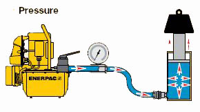
A hydraulic pump produces flow. Flow is the amount of fluid coming out of the pump.
Pressure occurs when there is resistance to flow.
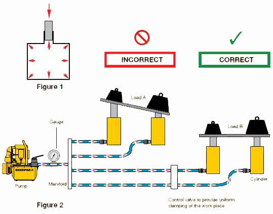
Pressure applied at any point upon a confined liquid is transmitted undiminished in all directions (Fig.1). This means that when more than one hydraulic cylinder is being used, each cylinder will pull or push at its own rate, depending on the force required to move the load at that point (Fig. 2). Cylinders with the lightest load will move first and cylinders with the heaviest load will move last (Load A), if the cylinders have the same capacity. To have all cylinders operate uniformly so that the load is being pulled or pushed at the same rate at each point, control valves (see Valve section) must be added to the system (Load B).
The amount of force a hydraulic cylinder can generate is equal to the hydraulic pressure times the “effective area” of the cylinder (see cylinder selection charts). Use the formula F = P x A to determine either force, pressure or effective area if two of the variables are known.
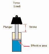
The volume of oil required for a cylinder (cylinder oil capacity) is equal to the effective area of the cylinder times the stroke.
The amount of hydraulic oil in the pump’s reservoir which can be used to activate one or more cylinders.
Pressure applied at any point Cylinder speed is determined by dividing the pump flow rate by the cylinder effective area.
Various seal types are used in our hydraulic equipment: O-rings, U-cups, Quad-rings and T-rings for static and dynamic applications such as rod-seal, piston-seal and wipers. Buna-N (nitrile rubber) and Polyurethane basic compounds are most frequently used – they offer the best performance and durability for most applications. Heat is a crucial factor in seal life. Maximum temperature for good seal life is 150°F (65°C). This is also the maximum temperature of Enerpac hydraulic oil. Above 150°F, the use of Viton and high temperature oil is necessary. Viton has a maximum temperature which is much higher than nitrate or polyurethane. Viton is however an extremely quick wearing material. In many cases Viton seals will have a short working life due to abrasive wear. Not all machine tool coolants are compatible with standard Enerpac seals. While most are, there are coolants that can harden or soften seals, which may result in free entry of contamination into the hydraulic cylinder. Using a high water based coolant may cause severe corrosive damage. This will often occur on fixtures where coolant has been allowed to pool for an extended period of time and evaporation has allowed it to concentrate. Drain and clean fixtures after use. Often Viton seals are an immediate cure for coolant attack on standard Enerpac seals. When using Viton seals in cylinders, seals in the power source must also be replaced by Viton because inevitably some coolant will enter the hydraulic system. Consult the coolant manufacturer to verify compatibility with any seal material. Cutting fluid suppliers will provide an application book on the compatibility of their fluids. If problems arise after previous successful use, or if problems persist, contact Enerpac.
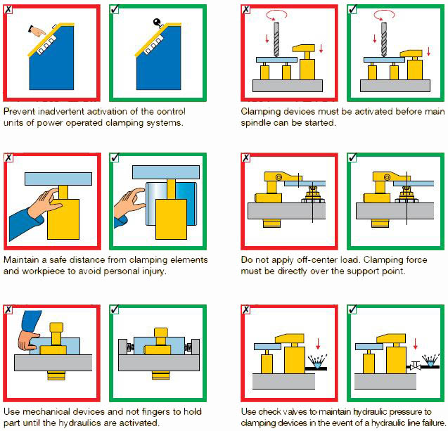
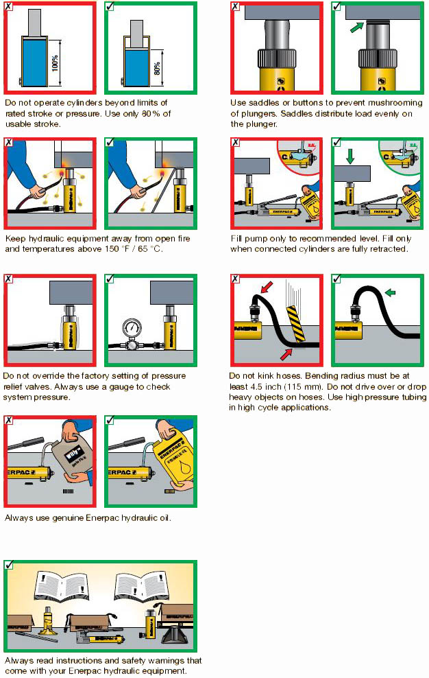
Hydraulic clamping can increase your machine shop’s efficiency by reducing setup time. Power clamping can also maximize output by reducing employee lost time due to the injuries that can occur with manual clamping. Although hydraulic operation moves the control of the clamping fixture to an area of greater safety, operators must still be alert to several common sense practices. And to that end we offer some DOs and DON’Ts, simple common sense points which apply to all Enerpac hydraulic products. The line drawings and application photos of Enerpac products throughout this catalog are used to portray how some of our customers have used hydraulics in industry. In designing similar systems, care must be taken to select the proper components that provide safe operation and fit your needs. Check to see if all safety measures have been taken to avoid the risk of injury and property damage from your application or system. Enerpac cannot be held responsible for damage or injury, caused by unsafe use, maintenance or application of its products. Please contact the Enerpac office or a representative for guidance when you are in doubt as to the proper safety precautions to be taken in designing and setting up your particular system. In addition to these tips, every Enerpac product comes with instructions spelling out specific safety information. Please read them carefully.
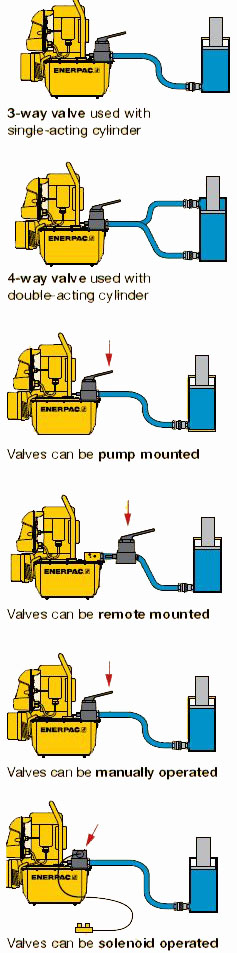
Hydraulic valves can be divided into 3 groups:
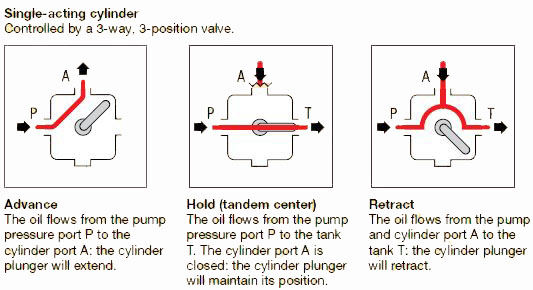
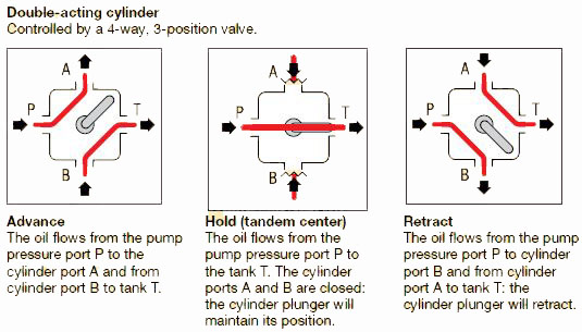
Directional control valves Ways – the (oil) ports on a valve. A 3-way valve has 3 ports: pressure (P), tank (T), and cylinder (A).A 4-way valve has 4 ports: pressure (P), tank (T), advance (A) and retract (B). Single-acting cylinders require at least a 3-way valve, and can, under certain instances, be operated with a 4-way valve. Double-acting cylinders require a 4-way valve, providing control of the flow to each cylinder port. Positions – the number of control points a valve can provide A 2-position valve has the ability to control only the advance or retraction of the cylinder. To be able to control the cylinder with a hold position, the valve requires a third position. Operation – the way to shift the valve into position. The valve position can be manually operated with the use of the handle. The valve position can be solenoid operated using power supply. Center configuration The center position of a valve is the position at which there is no movement required of the hydraulic component, whether a tool or cylinder. The most common is the Tandem Center. This configuration provides for no movement of the cylinder and the unloading of the pump. This provides for minimum heat build-up. The next most common is the Closed Center configuration, which is used mostly for independent control of multi-cylinder applications. This configuration again provides for no movement of the cylinder, but also dead-heads the pump, isolating it from the circuit. The use of this type of valve requires some means of unloading the pump to prevent heat build-up. Another commonly used valve configuration is Float Center. This type of valve allows the cylinder ports to drain pressure back to tank. Used with a pallet mounted pilot operated check, it allows the hydraulics to be disconnected from the pallet.
The direction of the oil flow can be controlled depending on valve type, valve positions and port functions.
The most common type of pressure control valve is the pressure relief valve. This valve is used to limit the maximum pressure in the hydraulic circuit. This valve should always be included in any hydraulic system to limit the circuit to a maximum safe pressure. When used in a system, design considerations should be made since the valve does not act instantly. As the pressure approaches the set point the valve will at first only permit a very small amount of oil to pass. It is only when the valve opens farther that the full flow will pass through the valve. From a practical standpoint, don’t set the relief valve with a hand pump and then use it with a power pump and vice versa. The point of operation will vary. Also because of this action, when used in application with a pressure switch, the pressure setting on the pressure switch should be set at least 500 psi (35 bar) lower than the point at which the relief valve opens. This will prevent rapid cycling of the motor on the pump because of the slight pressure loss thorough the relief valve. If the pressure settings must be closer than that the pressure switch should be monitoring the system pressure and a check valve should be added between the pump and the system. This will permit the pressure to bleed down on the pump through the relief and yet the check holds the pressure in the system, which is monitored by the pressure switch.
This valve controls the order in which various branches of the hydraulic circuit operate. It sequences the order of the actions. In practice, one part of the circuit will reach a preset pressure at which point the sequence valve will open and permit oil to flow to the secondary part of the circuit. When the flow to the secondary part of the circuit begins, the pressure in the first part of the circuit will remain at the set point permitting for example a work support to stay at its rated pressure as the swing cylinder clamps.
Everyone in maintenance encounters hose failures. Normally, the hose is replaced and the equipment goes back on line. Occasionally, however, the failures come too frequently – the same problems keep popping up. At this point, it is the task of maintenance to determine and correct the cause of these repeated failures. Failure to look into the problem, it the fault lies with the hose, will result in not only the repeated loss of hose lines, but may also cause unacceptable unscheduled downtime. If the problem lies with the equipment, failure to determine the cause could eventually result in the loss of the equipment. A little effort in the beginning can help you avoid a big headache in the long run. Every failure should be analyzed, even if that analysis is as basic as deciding that the failure was normal and acceptable. However, if the failure rate is unacceptable, you should probe a little deeper to determine the cause of the failure and to correct the problem. Hose failures fall into five major categories:
Beginning with a common cause of hose failure – improper application – compare the hose specifications with the requirements of the application. Pay particular attention to the following areas:
Check all of these areas against the requirements of the application. If they don’t match up, you need to select another hose. It’s a good idea, at this point, to call on your local hose distributor for assistance in selecting the proper hose. Aeroquip distributors are well equipped to perform this service for you. Distributor personnel attend special Aeroquip sponsored training courses in hydraulics and hose applications. Or, if your problem is particularly difficult, the distributor can call on the services of Aeroquip’s Field Engineering staff.
When you call on the distributor or manufacturer for help, make sure you provide all the information needed to solve your problem. Use the following check list when describing your problem:
By providing the distributor or manufacturer with complete information, you will get a better and quicker answer to your problem.
Other major causes of premature hose failure are improper assembly and installation procedures, involving anything from using the wrong fitting on a hose, to poor routing of the hose. Aeroquip provides excellent training material that offers assistance in combatting this problem. A little time spent in training could pay big dividends in reduced downtime. By making use of the free materials available from Aeroquip, you can improve your hose assembly and installation techniques. Contact Aeroquip or a distributor for details.
A crushed hose is an example of external damage. However, the hose may also be abraded and / or corroded. These are problems that can normally be solved once the cause is identified. The hose can be rerouted, clamped or an abrasion guard can be used. In the case of corrosion, the answer may be as simple as changing to a hose with a more corrosion resistant cover, or rerouting the hose to avoid the corrosive element.
Frequent or premature hose failure can be the symptom of a malfunction in you equipment. This is a factor that should be considered since prompt corrective action can sometimes avoid serious and costly equipment breakdown.
Occasionally, a failure problem will lie in the hose itself. A likely cause of a faulty hose is old age. Check the layline on the hose to determine the date of manufacture. The hose may have exceeded its useful life. If you suspect that the problem lies in the manufacture of the hose and you don’t jump to this conclusion until you have exhausted the other possibilities) contact your supplier. With modern quality control procedures, the odds of a faulty batch of hose being released for sale are extremely small. So make sure you haven’t overlooked some other problem.
A physical examination of the failed hose can often offer a clue to the cause of the failure. The following list suggests 23 symptoms to look for and the condition that could cause them.
.png)
.png)
.png)
.png)
.png)
.png)
.png)
.png)
.png)
Every industry has piping system leakage. This condition exists between the drawing board and the scrap dealer at all levels of industry including
In this article you will find a condensation of more than 40 years of Aeroquip’s experience in working with the basic types of fitting configurations that contribute to piping system leakage. The causes of most leakage are identified and appropriate corrective measures are suggested.
Remember – Seepers or weepers can be hard to locate
.png)
How it Works: This connection seals on the two mating 37° seats. Causes: Most of the leaks on this connection are due to lack of tightening or human error. You can’t tell if the nut has been tightened by just looking at the connection. If it is more than finger tight, you can’t tell from observation how much. Torque wrenches are good only when they are used. You must rely on the user to be sure torque wrenches are used on all joints. The user must depend on his memory to know if he has tightened all of the joints. Cure: Here are steps for an excellent method of tightening. Anyone can tell if the joint was tightened and how much.
.png)
| Line Size | Rotate Number of Hex Flats (For machined flares only) |
|---|---|
| -04 | 2-1/2 |
| -05 | 2-1/2 |
| -06 | 2 |
| -08 | 2 |
| -10 | 1-1/2 - 2 |
| -12 | 1 |
| -16 | 3/4 - 1 |
| -20 | 3/4 - 1 |
| -24 | 1/2 - 3/4 |
What to do if the joint leaks after it has been tightened properly: Disconnect the line and check for:
Remember – Many of the leakage problems on this type of connection won’t show until the unit has been in service for a few hours
How it Works: This connection seals with an O-Ring on the male against a chamber in the port. The use of straight thread O-Ring ports in place of pipe threads helps eliminate hydraulic leakage.
Causes:
Cures:
Why O-Ring lubrication is important:
.png)
.png)
.png)
What happens when the locknut and washer are not backed up prior to assembly:
.png)
.png)
| SAE J515 Straight Thread O-Ring | |||
|---|---|---|---|
| Dash Size | Tubing O.D. Ref. | W, Width, Diameter | Inside Diameter |
| -2 | 1/8 | .064±.003 | .239±.005 |
| -3 | 3/16 | .064±.003 | .301±.005 |
| -4 | 1/4 | .072±.003 | .351±.005 |
| -5 | 5/16 | .072±.003 | .414±.005 |
| -6 | 3/8 | .078±.003 | .468±.005 |
| -8 | 1/2 | .087±.003 | .644±.005 |
| -10 | 5/8 | .097±.003 | .755±.005 |
| -12 | 3/4 | .116±.004 | .924±.006 |
| -14 | 7/8 | .116±.004 | 1.048±.006 |
| -16 | 1 | .116±.004 | 1.171±.006 |
| -20 | 1-1/4 | .118±.004 | 1.475±.010 |
| -24 | 1-1/2 | .118±.004 | 1.720±.010 |
| -32 | 2 | .118±.004 | 2.337±.010 |
| Recommended torque values for straight fittings or locknuts | ||
|---|---|---|
| Dash Size | Inch-Pounds | |
| -04 | 160-175 | |
| -05 | 210-235 | |
| -06 | 260-290 | |
| -08 | 430-470 | |
| -10 | 520-570 | |
| -12 | 820-900 | |
| -16 | 1340-1470 | |
| -20 | 2620-2880 | |
| -24 | 1850-2040 | |
| -32 | 2620-2880 |
.png)
How it Works: The SAE 4-bolt split flange connection is a face seal. The flanged head which contains an O-Ring seal must fit squarely against the mating surface and be held there with even tension on all bolts. The flanged head protrudes past the split flange clamps by .010 to .030 inch. This is to ensure that the flanged head will make contact with the mating accessory surface, compressing the O-Ring to form the seal.
| Connection | Recommended Torue Inch-Pound | |
|---|---|---|
| Size | Code 61 | Code 62 |
| -08 | 175-225 | 175-225 |
| -12 | 250-350 | 300-400 |
| -16 | 325-425 | 500-600 |
| -20 | 425-550 | 750-900 |
| -24 | 550-700 | 1400-1600 |
| -32 | 650-800 | 2400-2600 |
| -40 | 950-1100 | - |
| -48 | 1650-1800 | - |
| Note: AIr wrenches tend to cause flange tipping |
.png)
Causes: This connection is sensitive to installation errors and bolt torqueing. Because of the flanged head protrusion and the flange clamp overhang,
the flanges tend to tip up in a seesaw fashion when the bolts are tightened on one end. This pulls the opposite end of the flange away from the
flanged head and, when hydraulic pressure is applied to the line, pushes the flanged head into a cocked position allowing seal extrusion.
.png) Cure: All bolts must be installed and torqued evenly. Finger tightening will help to get the flanges and shoulder started squarely. If lock washers are used, even more care must be taken.
A Second Cause: When excessive torque is applied to the bolts, the flanges often bend down until the bottom on the accessory. This also causes the bolt to bend outward.
Bending of the flanges and bolts tend to lift the flange off the shoulder in the center area between the long spacing of the bolts.
Cure: All bolts must be installed and torqued evenly. Finger tightening will help to get the flanges and shoulder started squarely. If lock washers are used, even more care must be taken.
A Second Cause: When excessive torque is applied to the bolts, the flanges often bend down until the bottom on the accessory. This also causes the bolt to bend outward.
Bending of the flanges and bolts tend to lift the flange off the shoulder in the center area between the long spacing of the bolts.
.png)
| Dash Size | L I.D. Ref (in) | M O.D. Ref (in) | N Dia. Ref (in) | SAE J120 O-Ring Size No. |
|---|---|---|---|---|
| -08 | 0.734 | 1.012 | 0.139 | 210 |
| -12 | 0.984 | 1.262 | 0.139 | 214 |
| -16 | 1.296 | 1.574 | 0.139 | 219 |
| -20 | 1.484 | 1.762 | 0.139 | 222 |
| -24 | 1.859 | 2.137 | 0.139 | 225 |
| -32 | 2.234 | 2.512 | 0.139 | 228 |
| -40 | 2.734 | 3.012 | 0.139 | 232 |
| -48 | 3.359 | 3.637 | 0.139 | 237 |
.jpg)
.png)
Aeroquip ORS® fittings and adapters are flat faced O-Ring seal connections that provide an excellent solution for leakage problems. These connections meet SAE J1452 performance requirements and are designed to handle working pressures up to 6000 psi. In order for Aeroquip ORS connections to virtually eliminate piping leaks, care must be taken to avoid the following problems, which may cause leakage.
Causes . . . . . . . . . . . . . . . . . . . . . . . . . . . . Cures
| ORS Recommended Torque Values | ||
|---|---|---|
| Connection | Swivel Nut Torque | |
| Dash Size | (in.-lbs.) | (ft.-lbs.) |
| -04 | 120-144 | 10-12 |
| -06 | 216-240 | 18-20 |
| -08 | 384-420 | 32-35 |
| -10 | 552-600 | 46-50 |
| -12 | 780-840 | 65-70 |
| -16 | 1104-1200 | 92-100 |
| -20 | 1500-1680 | 125-140 |
| -24 | 1800-1980 | 150-165 |
It is critical that the correct O-Ring is used. The proper dash sizes and dimensions are listed on the chart below.
| SAE J120 O-Ring Size Designation | ORS Tube Size | A (inches) | E (inches) |
|---|---|---|---|
| -011 | -4 | 0.301 | 0.07 |
| -012 | -6 | 0.364 | 0.07 |
| -014 | -8 | 0.489 | 0.07 |
| -016 | -10 | 0.614 | 0.07 |
| -018 | -12 | 0.739 | 0.07 |
| -021 | -16 | 0.926 | 0.07 |
| -025 | -20 | 1.176 | 0.07 |
| -029 | -24 | 1.489 | 0.07 |
.png)
| Torque values for SAE O-Ring boss ends, when used with ORS connections* per SAE J1453 | ||||
|---|---|---|---|---|
| Straight Fitting of Locknut Torque | ||||
| Dash Size | Thread Size Inch | (in. - lbs.) | (ft. - lbs) | |
| -03 | 3/8-24 | 96-120 | 8-10 | |
| -04 | 7/16-20 | 168-192 | 14-16 | |
| -05 | 1/2-20 | 216-240 | 18-20 | |
| -06 | 9/16-18 | 288-312 | 24-26 | |
| -08 | 3/4-16 | 600-720 | 50-60 | |
| -10 | 7/8-14 | 864-960 | 72-80 | |
| -12 | 1 1/16-12 | 1500-1620 | 125-135 | |
| -14 | 1 3/16-12 | 1920-2160 | 160-180 | |
| -16 | 1 5/16-12 | 2400-2640 | 200-220 | |
| -20 | 1 5/8-12 | 2520-3360 | 210-280 | |
| -24 | 1 7/8-12 | 3240-4320 | 270-360 | |
| *Increased torque values are required for the increased pressure capabilities of ORS Connections |
For virtually all types of fluid connectors involving O-Rings, there are common guidelines that should always be followed.
.png)
.png)
.png)
Pipe threads are not recommended for high pressure applications, since they tend to leak more than any other style of connection NPT – National Pipe Taper NPTF – National Pipe Taber Fuel (Dryseal) NPT threads are likely to leak much more than Dryseal pipe threads. Either kind of pipe thread will leak if under tightened. There is not a general accepted standard for tightening either style of tapered threads. The tightening requirements change with each reuse and / or type of sealant used. Use a good pipe sealant on the male threads. When applying pipe sealant, do not put any on the first two threads. Over tightening may crack the female port.
| Metric Pressure Conversion Tables | ||||||||||
|---|---|---|---|---|---|---|---|---|---|---|
| Bar to PSI (Multiply Bar by 14.5=PSI) | ||||||||||
| Bar | 0 | 1 | 2 | 3 | 4 | 5 | 6 | 7 | 8 | 9 |
| PSI | PSI | PSI | PSI | PSI | PSI | PSI | PSI | PSI | PSI | |
| 0 | - | 14.5 | 29 | 43.5 | 58 | 72.5 | 87 | 101.5 | 116 | 130.5 |
| 10 | 145 | 159.5 | 174 | 188.5 | 203 | 217.5 | 232 | 426.5 | 261 | 275.5 |
| 20 | 290 | 304.5 | 319 | 333.5 | 348 | 362.5 | 377 | 391.5 | 406 | 420.5 |
| 30 | 435 | 449.5 | 464 | 478.5 | 493 | 507.5 | 522 | 536.5 | 551 | 565.5 |
| 40 | 580 | 594.5 | 609 | 623.5 | 638 | 652.5 | 667 | 681.5 | 696 | 710.5 |
| 50 | 725 | 739.5 | 754 | 768.5 | 783 | 797.5 | 812 | 826.5 | 841 | 855.5 |
| 60 | 870 | 884.5 | 899 | 913.5 | 928 | 942.5 | 957 | 971.5 | 986 | 1000.5 |
| 70 | 1015 | 1029.5 | 1044 | 1058.5 | 1073 | 1087.5 | 1102 | 1116.5 | 1131 | 1145.5 |
| 80 | 1160 | 1174.5 | 1189 | 1203.5 | 1218 | 1232.5 | 1247 | 1261.5 | 1276 | 1290.5 |
| 90 | 1305 | 1319.5 | 1334 | 1348.5 | 1363 | 1377.5 | 1392 | 1406.5 | 1421 | 1435.5 |
| 100 | 1450 | 1464.5 | 1479 | 1493.5 | 1508 | 1522.5 | 1537 | 1551.5 | 1566 | 1580.5 |
| Metric Pressure Conversion Table | ||||||||||
|---|---|---|---|---|---|---|---|---|---|---|
| Megapascal (MPa) to PSI (Multiply MPa by 145=PSI) | ||||||||||
| MPa | 0 | 1 | 2 | 3 | 4 | 5 | 6 | 7 | 8 | 9 |
| PSI | PSI | PSI | PSI | PSI | PSI | PSI | PSI | PSI | PSI | |
| 0 | - | 145 | 290 | 435 | 580 | 725 | 870 | 1015 | 1160 | 1305 |
| 10 | 1450 | 1595 | 1740 | 1885 | 2030 | 2175 | 2320 | 2465 | 2610 | 2755 |
| 20 | 2900 | 3045 | 3190 | 3335 | 3480 | 3625 | 3770 | 3915 | 4060 | 4205 |
| 30 | 4350 | 4495 | 4640 | 4785 | 4930 | 5075 | 5220 | 5365 | 5510 | 5655 |
| 40 | 5800 | 5945 | 6090 | 6235 | 6380 | 6525 | 6670 | 6815 | 6960 | 7105 |
| 50 | 7250 | 7395 | 7540 | 7685 | 7830 | 7975 | 8120 | 8265 | 8410 | 8555 |
| 60 | 8700 | 8845 | 8990 | 9135 | 9280 | 9425 | 9570 | 9715 | 9860 | 10005 |
| 70 | 10150 | 10295 | 10440 | 10585 | 10730 | 10875 | 11020 | 11165 | 11310 | 11455 |
| 80 | 11600 | 11745 | 11890 | 12035 | 12180 | 12325 | 12470 | 12615 | 12760 | 12905 |
| 90 | 13050 | 13195 | 13340 | 13485 | 13630 | 13775 | 13920 | 14065 | 14210 | 14355 |
| 100 | 14500 | 14645 | 14790 | 14935 | 15080 | 15225 | 15370 | 15515 | 15660 | 15805 |
| Metric Pressure Conversion Table | ||||||||||
|---|---|---|---|---|---|---|---|---|---|---|
| Kg/cm2 to PSI (Multiply Kg/cm2 by 14.22=PSI) | ||||||||||
| Kg/cm2 | 0 | 1 | 2 | 3 | 4 | 5 | 6 | 7 | 8 | 9 |
| PSI | PSI | PSI | PSI | PSI | PSI | PSI | PSI | PSI | PSI | |
| 0 | - | 14.22 | 28.44 | 42.66 | 56.88 | 71.1 | 85.32 | 99.54 | 113.76 | 127.98 |
| 10 | 142.2 | 156.42 | 170.64 | 184.86 | 199.08 | 213.3 | 227.52 | 241.74 | 225.96 | 270.18 |
| 20 | 284.4 | 298.62 | 312.84 | 327.06 | 341.28 | 355.5 | 369.72 | 383.94 | 398.16 | 412.38 |
| 30 | 426.6 | 440.82 | 455.04 | 469.26 | 483.48 | 467.7 | 511.92 | 526.14 | 540.36 | 554.58 |
| 40 | 568.8 | 583.02 | 597.24 | 611.46 | 625.68 | 639.9 | 654.12 | 668.34 | 682.56 | 696.78 |
| 50 | 711.0 | 725.22 | 739.44 | 753.66 | 767.88 | 782.1 | 796.32 | 810.54 | 824.76 | 838.98 |
| 60 | 853.2 | 867.42 | 881.64 | 895.86 | 910.08 | 924.3 | 938.52 | 952.74 | 966.96 | 981.18 |
| 70 | 995.4 | 1009.62 | 1023.84 | 1038.06 | 1052.28 | 1066.5 | 1080.72 | 1094.94 | 1109.16 | 1123.38 |
| 80 | 1137.6 | 1151.82 | 1166.04 | 1180.26 | 1194.48 | 1208.7 | 1222.92 | 1237.14 | 1251.36 | 1265.58 |
| 90 | 1279.8 | 1294.02 | 1308.24 | 1322.46 | 1336.68 | 1350.9 | 1365.12 | 1379.34 | 1393.56 | 1407.78 |
| 100 | 1422.0 | 1436.22 | 1450.44 | 1464.66 | 1478.88 | 1493.1 | 1507.32 | 1521.54 | 1535.76 | 1549.98 |
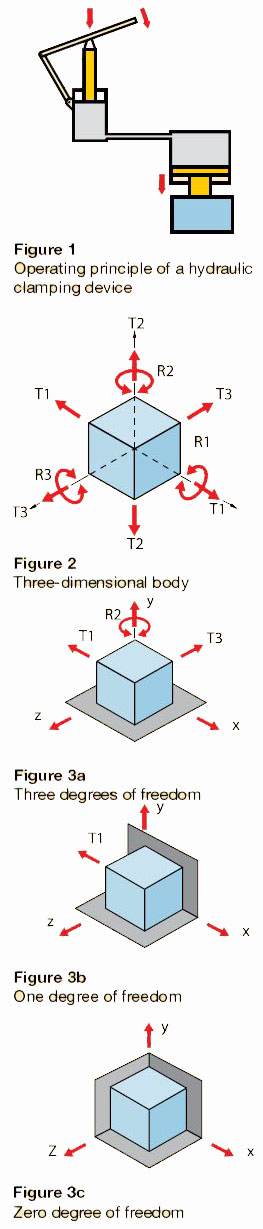
1.2.1 Clamping Plunger - A device that applies clamping force to the workpiece. 1.2.2 Workpiece - The part or material that is to be held in place. 1.2.3 Pressure Piston - A device used to apply pressure to a hydraulic medium. 1.2.4 Hydraulic Medium - A fluid used to transmit the pressure created by applying a force to the pressure piston
The hydraulic clamping process consists of properly applying the forces created by a hydraulic clamping system to secure a workpiece. A hydraulic clamping system consists of the components illustrated in Figure 1, which shows the basic arrangement and operating principle of the use of hydraulic media. Any such process using hydraulic fluids for clamping purposes may be referred to as a hydraulic clamping system. The operating pressure provided by hydraulic fluids in clamping systems can reach a maximum of 5000 psi (350 bar), allowing the application of considerable clamping forces even when using compact clamping cylinders. When properly designed and controlled, the hydraulic clamping mechanism will prevent the workpiece from moving (sliding, twisting, etc.) when machining or other forces are applied, yet will not cause an unexpected permanent distortion to occur in the workpiece.
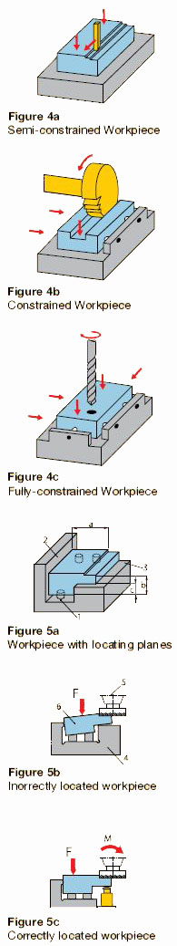
2.1.1 Locating a Body - The term “locating” refers to the process of positioning the workpiece inside the clamping device, and holding it in position for the necessary machining. Only workpieces that are correctly held can be consistently machined within specified tolerances. 2.1.2 Limiting the degrees of freedom - The process of locating and holding a workpiece may be referred to as “limiting the degrees of freedom.” Any motion of a workpiece in any possible direction is considered to represent one degree of freedom. A three-dimensional workpiece therefore possesses six degrees of freedom, as shown in Figure 2. These six degrees of freedom consist of the translational motions “T” in x, y, and z direction, and the rotational motions “R” turning about the x, y, and z axes. The degrees of freedom that a given workpiece or body possesses may be reduced by introducing reference planes that pass through any two axes. For example, the plane in Figure 3a limits movement to travel in x and z directions and rotation about the y-axis. By defining this fixed plane, the workpiece can thus be limited or constrained to three degrees of freedom. Another two degrees of freedom may be constrained by introducing a second reference plane, as shown in Figure 3b. This reference plane limits movement to translational motion in the x direction. Constraining the last degree of freedom can be accomplished by defining a third reference plane as shown in Figure 3c. 2.1.3 Locating a workpiece - The process of locating and holding a necessarily require the elimination of movement in all six degrees of freedom, the following three locating techniques are used in actual practice. Figure 4a: Semi-constrained Workpiece. The workpiece is held in one plane only (elimination of three degrees of freedom). Figure 4b: Constrained Workpiece. The workpiece is held by two planes (elimination of five degrees of freedom). Figure 4c: Fully-constrained Workpiece. The workpiece is held by three planes (elimination of six degrees of freedom).
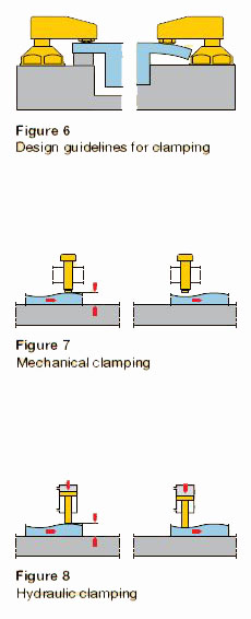
2.1.4 Avoiding over-locationSince the distance between the locating planes (1) and (3) is constant in this device, the dimension c differs between individual workpieces. This over-location therefore gives rise to machining error. Figure 5c: Shows how to locate a workpiece correctly. To avoid tilting the workpiece, the torque “M” transferred from the workpiece (5) to the body to be machined (6) must be balanced by an appropriate counter-torque. This counter-torque is created by the clamping force “F.” Over-location may also occur if a workpiece (Figure 5) is limited by too many locating points. The introduction of more than three locating points along the bearing surface, or more than two points in the guide plane, or more than one point in the supporting plane may lead to undesirable workpiece motion, and thus adversely affect the precision of the resulting product. Any additional support points must be adjustable. If the workpiece to be machined must be supported to avoid deflection, then all other bearing points must be defined as variables and must be determined in relationship to the workpiece being machined. The location process is subject to a number of design guidelines, but exceptions are possible.
The term “clamping” refers to the secure fastening of an already positioned workpiece in a clamping device for machining purposes. Locating and clamping may be viewed as a combined operation. Clamping is invariably associated with force transmission through the device. The force vector should, as far as possible, describe a straight line from the application point of the clamping force through the workpiece to the bearing points. As with clamping, locating is subject to a number of design guidelines, although exceptions are possible:
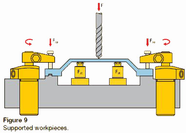
Mechanical clamping elements are usually used for simple clamping devices. However, mechanical clamping elements may be converted to hydraulic ones by inserting cylinders between the clamping element and the workpiece. In addition, mechanical elements may also be combined with hydraulic clamping elements. Clamping may be subject to errors that cause deformation of the clamped workpiece. Since such deformations must not affect the function of the workpiece, all conceivable locating and supporting techniques, as well as the best possible directed transmission of the clamping force through the workpiece, should be considered. It is recommended that clamping forces be estimated to prevent excessively high clamping forces and possible deformation of the workpiece. Deformation of the workpiece may also be avoided by selecting a suitable shape (for example, a sphere) for the clamping points and the locating points.
4.1 Supported workpiece - The workpiece requires support to ensure
functional force transmission between the tool, the workpiece, and the clamping
device, and/or to protect the workpiece from deformation (such as deflection at
points with a thin cross-section) due to machining forces, gravitational forces,
and clamping forces. Workpiece support also acts to eliminate the resulting machining
errors (Figure 9).
In addition, surface quality may be improved and the service life of the tool
prolonged with the use of an optimum supporting mechanism. The three-dimensional
position of a workpiece, however, should not be defined by its support. It is
preceded sequentially by the locating process and also has a lower priority.
 4.2 Supporting options for bent workpieces
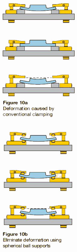
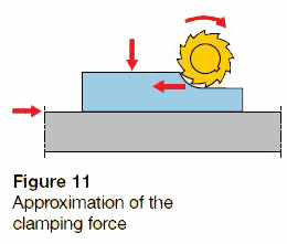
A workpiece is considered to be supported even if it must be supported by frequently mobile and variable elements surpassing the theoretical maximum number of locating points. An example of this would be an unstable workpiece that easily vibrates. When a deformed workpiece must be held and clamped in all three planes without altering its shape, it is possible to use a technique involving self adjusting spherical surfaces. In this case the bearing surfaces, the close tolerance bolts, the limit stops, and the vertically adjustable supporting and clamping elements must be equipped with spherical surfaces. The illustrations in Figure 10 illustrate two different clamping methods. It shows deformation of a workpiece caused by conventional clamping (Figure 10a). As a result of this deformation, the surface area of the workpiece exhibits a greater degree of deformation when unclamped. This deformation, which is convex in shape, may be attributed to the fact that the workpiece assumes its original, deformed shape (c), as soon as the clamping pressure is released. The clamping points illustrated in Figure 10b are spherically shaped, and can therefore largely adapt to the workpiece curvatures (b). The machined surface is therefore flat, and the workpiece is only exposed to possible internal stresses that may be released by machining. 4.3 Determination of the clamping force - It is important to ensure that a workpiece that is clamped inside a device is not moved from its position by the clamping force and the subsequent action of the cutting force. This risk of movement may be minimized by applying the clamping force to the solid bearing surfaces of the device (Figure 11).
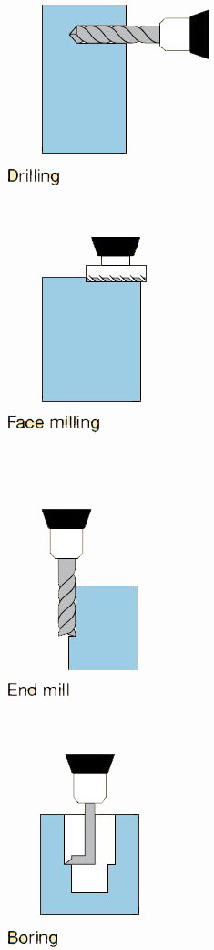
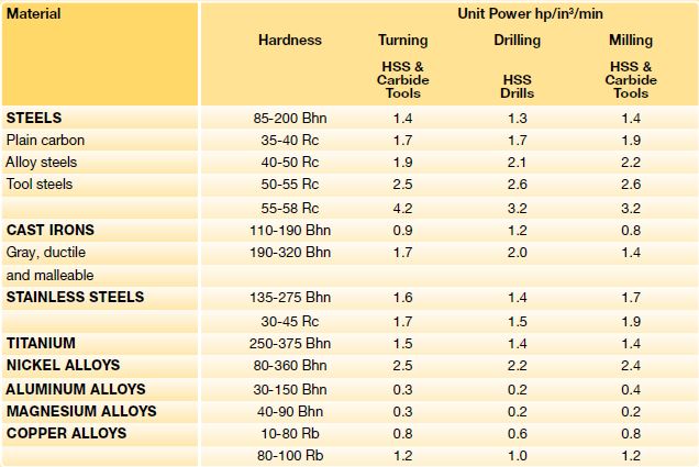
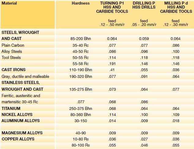
This introduction will help you use information provided by tool manufacturers in the application of their tools. Estimating cutting forces being transferred into the workpiece is just one tool to use in a competitive workholding environment. The information presented here is only to be a guideline and not the final decision. Use this information with a cutting tool brochure you get from your cutting tool supplier as an aid in determining your cutting forces. Much of the calculations presented here are readily available from many sources. Your cutting supplier may even have a slide chart you can obtain to do equations for you. The operations described here include boring, drilling, end milling and face milling. Drilling involves using a multi-fluted tool with a helix spiral. The tool is driven in as it is rotated to create a round hole. End Milling uses a multi-fluted rotary tool with or without removable (inserts) teeth to remove material along the edge of the workpiece. The cut is usually very shallow and the depth is many times the thickness of the cut. Face Milling involves a very shallow depth, but a very wide cut. Cutters can range up 12 inches (300 mm) or more in diameter and can have many replaceable teeth (inserts). These examples are only a very small sample of operations that can use hydraulic workholding.
These cutting force examples involve face milling. The largest use of hydraulic workholding is by far for some sort of milling operations. 1 Imperial system Cutting Force (Pounds) = Spindle Horsepower x 26400 (Horsepower to foot pounds per minute at 80% efficiency)/ Cutting Speed (In tool surface feet per minute) Spindle Horsepower = Unit Power (Horsepower per cubic inches of material removed per minute) x Material removal rate (Cubic Inches per Minute) Material removal rate (Cubic inches per minute) = Width of the cut (Inches) x Depth of the Cut (Inches) x Feed per cutter tooth (Inches) x Number of cutter teeth x Spindle RPM Example An 8-inch diameter cutter with 10 teeth (inserts) is machining low silicon aluminum at 3000 SFM (surface feet per minute). First, you must convert surface feet/ minute into tool RPM/Solving Tool RPM= SFM Diameter (Inch) x .2618 = 1432 Tool RPM Now you can determine your material removal rate. An independent tool catalog lists a feed per tooth of 0.008" maximum at 3000 SFM at cut depth of 0.1". This gives 8" (diameter cutter) x 0.100" (cut depth) x 0.008" (feed per tooth) x 10 (number of teeth) x 1432 (spindle RPM)= 91.6 cubic inches per minute material removal rate. Next, spindle horsepower is found using unit HP from the table Spindle Horsepower = 91.6 x 0.4 (Unit Horsepower for Aluminum with a dull tool) = 36.6 HP. Note this Horsepower is for fixture design and not for machine tool horsepower requirements. For example a true 40 HP machine can remove aluminum well over 200 cubic inches per minute.
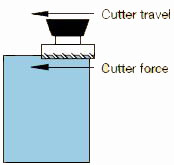
Using the original formula: 36.6 hp x 26,400/3000 SFM = 322 lbs. 3000 SFM of force being transmitted into the work. Force is transmitted in the same direction as the cutter movement. In other words, if the cutter moves right to left in the diagram below, the cutter force is transmitted from right to left. Using a safety factor of 2 for rigid clamping gives 644 pounds in line parallel to the line force and 483 pounds using an elastic medium such as hydraulics with a safety factor of 1.5. Note this force does not take into account any sort of friction factors if you plan on relying on friction force between a swing cylinder and the workpiece. For example: The coefficient of friction for lubricated aluminum is .12 (flooded with coolant) this same 483 pounds of force becomes 483/.12 = 4025 pounds. This uses clamp force only and does not take into account any direct forces that may be developed by the cylinders that located the workpiece against fixed locators. Cutting Force = Spindle Hp x 26406 / Cutting Speed Spindle Horsepower to foot-pounds at 80% efficiency Cutting force in Pounds Cutting tool surface feet per minute MRR = W x D x F x N x RPM W = Width of cut (in) D = Depth of cut (in) F = Feed per tooth (in) N = Number of cutter teeth RPM = Spindle speed Material Removal Rate (in3/min) Tool RPM = SFM Diameter x 0.2618 1 SFM = Surface Feet per Minute Unit Power for Dull Tools (Imperial System)
Metric System Cutting Force (Newtons) = Spindle Power (kW) x 48000 (80% efficiency) / Cutting Speed (Meters per minute). Spindle Power = Unit Power (kilowatts per cubic centimeters of material remove per minute) x Material removal rate (cubic centimeters per minute). Material removal rate (Cubic centimeters per minute) = Width of cut (mm) x depth of cut (mm) x feed per tooth (mm) x number of teeth x spindle RPM/1000. Example: A 200 mm cutter with 10 teeth is machining low silicon aluminum at 1000 MPM (meters per minute). Solving Tool RPM = MPM x 1000 Diameter (mm) x p (= 1592 Tool RPM) The same tool catalog lists a feed per tooth of 0.2 mm at 1000 MPM and a cutting depth of 2.5 mm. This gives an 200 mm cutter x 2.5 mm depth x 0.2 mm feed x 10 teeth x 1592 Tool RPM/1000 = 1592 cm3/min. Spindle power = 1592 x 0.018 = 28.7 kW This too is power from a fixture design standpoint; the actual operation will use less power than indicated here. Using the original formula transposed is: Cutting Force 1378 (Newtons) = 28.7 (kW) x 48000 (80% efficiency) / 1000 (MPM cutting speed). Multiply by a safety factor of 2 for rigid clamping and by 1.5 for elastic clamping (hydraulic). This calculation does not take into account coefficients of friction when using clamp cylinders. For example, if the aluminum has a coefficient of .12 (flooded with coolant), the clamping force becomes 1378/.12 = 11483 Newtons of force. This calculation does not take into account forces being generated by the fixture positioning cylinders. Use these numbers and set up your hydraulic system to run at about 50 to 75% of its rated pressure. This leaves some reserve for a later date when the process is optimized and you need more holding/ clamp force for higher speeds and feeds. If you design to the maximum now, you have nothing in reserve. Unit Power for Dull Tools (Imperial System)
This is the most important consideration when installing the cylinder. When cylinders are shipped, the ports are usually securely plugged with plastic plugs which should not be removed until the piping is to be installed. All piping should be thoroughly clean, to include the removal of all threading and flaring burrs or chips, before making the connection to the cylinder ports. One chip can cause premature failure of the cylinder or other system components.
Improper alignment will result in excessive cylinder wear. Check to assure rod alignment between the cylinder and its mating component on your machine in both the extended and retracted positions.
Cylinders operating in areas where there is weld splatter, fast drying chemicals, paint, excessive heat or other hazardous conditions, should have covers or shields to prevent damage to the rod and rod seals
The use of high strength alloy steel mounting bolts 1/16” smaller than the hole size is recommended. After final alignment, foot mounted cylinders should de dowel pinned in place.
Lubricated pillow blocks designed for close tolerance applications should be used. It is important to rigidly mount and align the pillow blocks so that the trunnion pins will not be subjected to any extreme bending moments. The rod end should be pivoted with the pivot pin in line and parallel to the axis of the trunnion pins.
The use of high strength alloy steel mounting bolts is recommended. Shear keys should be used to reduce the stress on the mounting bolts created by the normal push and pull forces created by the cylinder cycle.
The controlled diameter rod busing extension can be used as a pilot to locate the flange mount. Dowel pins should be used after the cylinder is mounted and aligned to prevent shifting.
This type of cylinder must be pivoted at both ends and the pins must be in line and parallel to each other. After the cylinder is mounted, the customer should check to assure that the cylinder is free to swing through its working arc without interference from other machined parts.
When changing rod seals, extend the piston rod 3” or more if possible, being sure to support the rod at all times. Remove the retainer plate screws (if tie-rod nuts have to be removed, refer to the nut torque specification on this page when reassembling the cylinder), retainer plate and outer bushing. Using an eye hook or thin screwdriver, pry the vees from the end cap cavity (if low pressure air is applied to the rod end port, this will help to force the vees from the cavity). The new set of vees should be assembled into the cavity separately and lubed with soft vee in the center. Replace the rod wiper in the busing and reassemble the cylinder.
When changing piston seals, extend the piston rod 3” or more if possible, being sure to support the piston rod and the piston at all times. *Remove the tie-rod nuts, blind end cap, the barrel and the piston seals. A light grease, compatible with the system fluid, grease, compatible with the system fluid, should be used on the rings and u-cup seals for smooth assembly. Install the u-cup piston seals, scarf cutting on only the back-up washers. Then install the cast iron rings with the joints in opposite directions. To reassemble start the piston into the tube, compressing the cast iron rings using twine or a ring compressor. When the piston u-cup seal is to the edge of the barrel, use a thing rounded blade to start the lip of the u-cup, making sure the entire lip is started before moving the piston further into the tube. *Note: When a cylinder has been disassembled this far, the barrel seals should at least be inspected, if not replaced.
When replacing barrel seals, use the same method of disassembling the cylinder as used when replacing piston seals. The barrel seal is a gasket which is layed into the end cap tube groove first. Then position the end caps squarely on the tube (check to make sure port location is correct), and firmly force or tap the end cap over the tube until it bottoms. Check to make sure the gasket did not move and then finish assembling the cylinder.
Often times, cylinders are delivered before a customer is prepared to install them and must be store for a period of time. When storage is required:
For the compelete instructions from Flairline for heavy duty cylinder maintenace see the Maintenance Instructions PDF.
Instructions for series F/O/H/D/M/DM/I/DI/SI/DSI
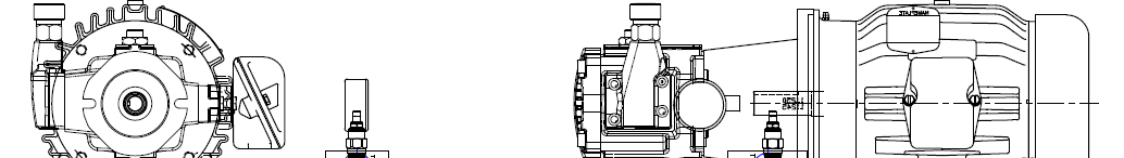
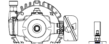
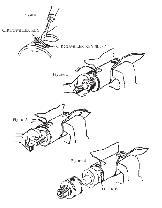
Remove any plumbing from cylinder ports; wrap brrel in heavy cloth to prevent damage to barrel. Place cap end of cylinder barrel in vise. As you rotate head counter clockwise, use a screw driver to lift end of circumflex key clear of slot (figure 1 below).
Continue rotation of head, and circumflex key will feed out of slot (figure 2 below). Gripping rod, pull forward. Head, rod and piston will come out of barrel (figure 4 below). Screw head off rod threads for ease of clearing rod packing.
Slide head end back in barrel to support barrel and follow same procedure as above to remove circumflex key from cap end (figure 3 below). If cylinder has been used in wet or moist external conditions for a long period, circumflex key may be corroded. If this is the case, apply penetrating oil into the lock slots prior to disassembly.
Replace piston (if necessary), rod packings and wiper and all static seals. Clean I.D. of tube thoroughly. Lubricate rod packings and O.D. of piston prior to assembly. To reassemble cylinder, follow above procedure, except heads wil be turned clockwise after circumflex key is engaged in tang hole in circumflex groove of head. Turn clockwise until circumflex is completely into groove and cylinder port in head is aligned with port hole in barrel. To get head end over rod threads without damaging packing and wiper, wrap rod threads with tape.
NOTE: Lock nut must be replaced when piston is replaced (Figure 4). DO NOT use old lock nut. Complete packaging kits and lubricants are available for all Flairline cylinders. Please contact us to order.
Pressure in a confined body of fluid acts equally in all directions, and always at right angles to the containing surfaces.
The absolute pressure of a confined body of gas varies inversely as its volume, provided its temperature remains constant.
If the temperature of a gas is raised, its volume increases by the same ratio, providing the pressure remains constant.
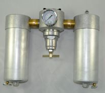
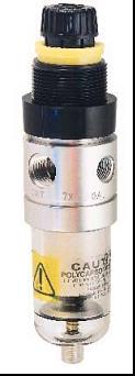
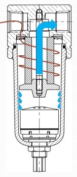
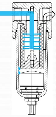
The purpose of a particulate filter is to remove moisture and contaminants from compressed air. The air entering the filter is passed through a whirl disc that creates high centrifugal force with minimal pressure drop. The whirling action forces liquids and solids against the inside of the bowl where gravity pulls them to the quiet zone below the baffle where they can be drained out. The air then flows through the element where smaller particles are removed and the dry, filtered air passes downstream.
The purpose of a coalescing filter is to provide a very fine degree of filtration, removing moisture, oil, and particulate matter as small as .01 micron. The air flows from the inside to the outside of the element through progressively larger media. As contamination moves through the element, solid particles are trapped and liquids are formed into large droplets. As the air exits the element surface, tension holds the liquids and allows them to drain to the bottom of the bowl.
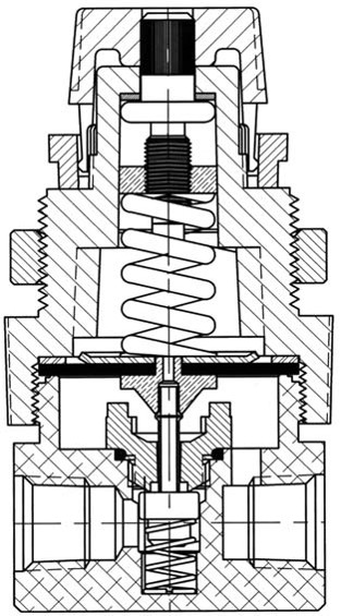
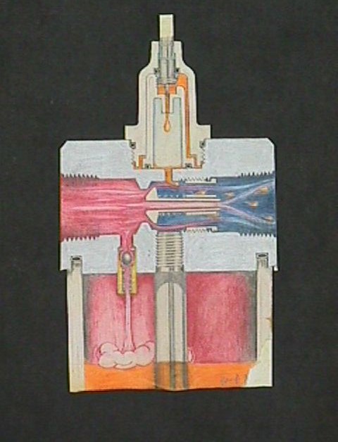
The purpose is to reduce the higher pressure provided by a plant’s air compressor to a lower, more suitable level for each machine in which the air is used. A regulators is a three way, normally closed, poppet valve which is closed by excessive pressure on its diagram.
The purpose of a lubricator is to introduce an oil mist into compressed air to lubricate downstream equipment. Oil is introduced into the air via a venturi valve and is broken into a fine mist by high velocity air flow.
The purpose of the integral filter regulators is to provide the benefits of a pneumatic filter and regulator in one device. Its' functionality is indentical to the mechanics of individual air prep units.